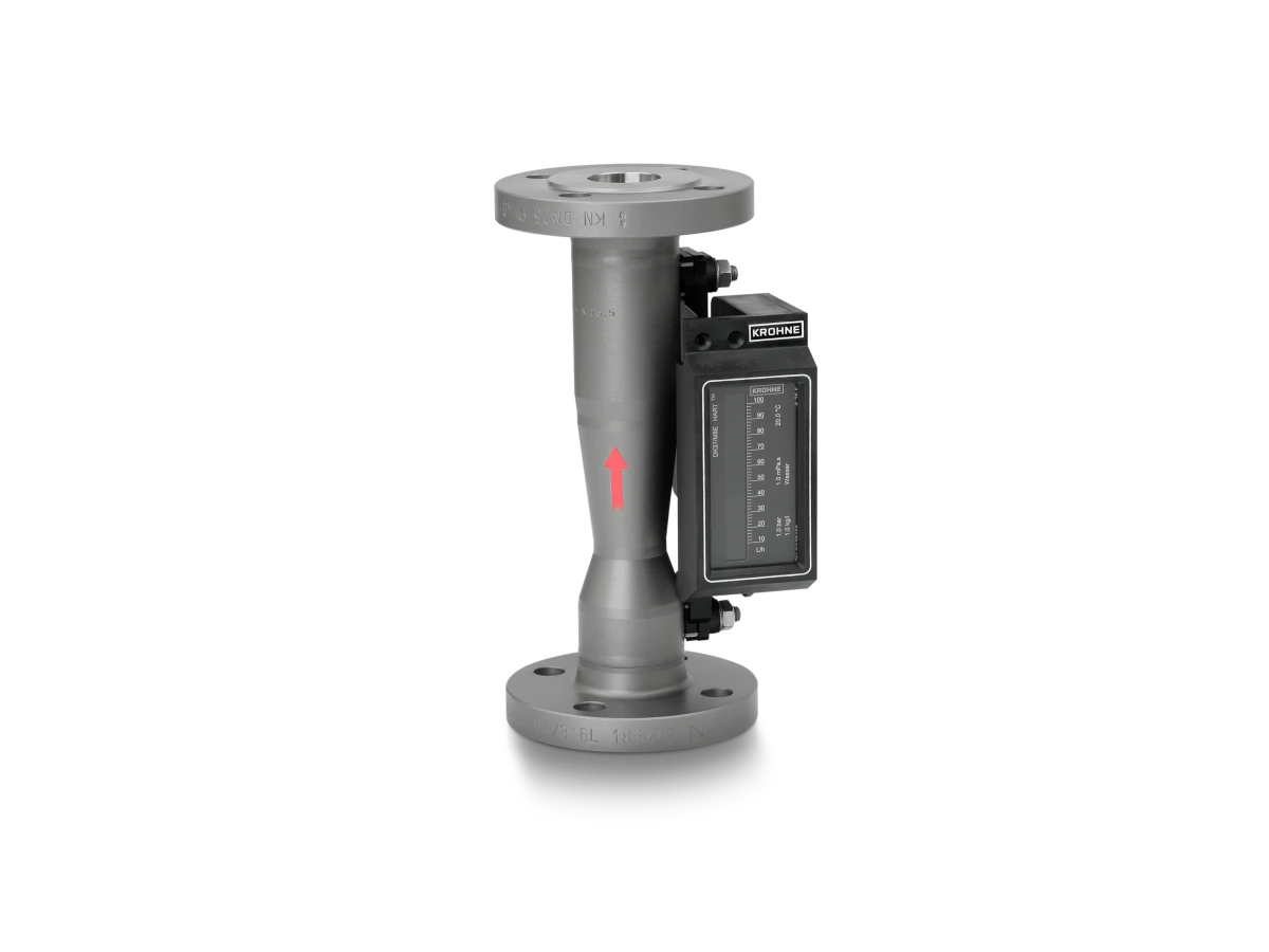
H250 M8
Variable area flowmeter for liquids and gases
- Mechanical or with electronic bargraph indicator (4…20 mA/HART®)
- Flange: DN15…25 / ½…1″; also NPT, G, hygienic connections, etc.
- -40…+200°C / +392°F; max. 145 barg / 2102 psig
Variable area flowmeter for liquids and gases
The H250 M8 is a variable area (VA) flowmeter with electrical signal output and bargraph indication or mechanical indication with two optional limit switches. The compact flowmeter allows space-saving installation. It is thus highly suitable for installation in limited spaces. The H250 M8E version features magnetic sensors recording the position of the float without contact or hysteresis. Standard system operation is with a linear analogue output in 2-wire technology (4…20 mA). The H250 M8M version operates without auxiliary power. The flow value as well as the optional two limit switch setpoints are displayed on the scale. It has approvals for use in hazardous areas and comes with a wide range of process connections.
For liquids and gases
Variable area float
Liquids, Gases
max. 145 barg/2102 psig
-40…+200°C/-40…+392°F
Measuring tube Austenitic stainless steel (1.4404/316L), Austenitic alloy (2.4610/Alloy C4), Nickel alloy (2.4360/Alloy 400), Titanium alloy (3.7035/Ti-Grade 2), Nickel-chrome-molybdenum-tungsten alloy (2.4819/Alloy C276), Nickel-chromium-molybdenum-niobium alloy (2.4856/Alloy 625), Austenitic stainless steel (1.4547/6Mo)
None
Austenitic stainless steel (1.4404/316L), Nickel alloy (2.4360/Alloy 400), Austenitic alloy (2.4610/Alloy C4), Nickel-chrome-molybdenum-tungsten alloy (2.4819/Alloy C276), Nickel-chromium-molybdenum-niobium alloy (2.4856/Alloy 625), Titanium alloy (3.7035/Ti-Grade 2), Austenitic stainless steel (1.4547/6Mo)
Flange connections EN (1092-1): DN15…50
ASME (B 16.5): ½…2″
JIS (B 2220): 15…150A
G½, G¾, G1
½ NPT, ¾ NPT, 1 NPT
Clamp (DIN 32676): DN15, DN25, DN32, DN40, DN50, DN80
Clamp (ISO 2852): 25, 40, 51, 76.1
Tri-Clamp: ½”, 1″, 2″
(DIN 11851): DN15, DN25, DN40, DN50, DN80
(DIN 11864-2): DN15, DN25, DN50, DN80
(SMS 1146): 25 mm, 51 mm, 76 mm
Certificates/Approvals Ex ATEX, cQPSus, IECEx, NEPSI, EAC Ex
Certificates/Approvals Safety SIL 2
Analogue outputs 4…20 mA
Discrete outputs Limit switches
Digital outputs HART®
Product features and options depend on device configuration: Contact us to make sure that your preferred functionality can be combined in one device.